
Building a Figma Plugin with React + Tailwind
Recently, I got in touch with a well known UI Designer and Teacher, Erik Kennedy, and offered to create a Figma plugin based on his gradient generator tool. This took me on a little journey into the world of Figma plugin development armed with React, Tailwind and a little knowledge of trigonometry and 2D matrices!
The gradient generator plugin is now live on the Figma Community, and you can start using it here!
Contents
- Background - What the plugin is for
- Setting up the Figma Plugin Development Environment
- How the plugin window communicates with the Figma canvas
- Generating the gradients
- Applying the gradients to layers
- Live Updates in the Canvas
- Saving Data to Figma Layers (+Rehydrating)
- Wrapping Up + Publishing
- Supplementary Material
Background - What the plugin is for
I’m a developer by trade, I’ve often viewed myself as more “analytical’ than creative. Nevertheless, I’ve always fond of the idea of being able to come up with UI designs by myself that are both functional and aesthetic. This isn’t an uncommon goal for developers, and a couple of years back I discovered Erik Kennedy’s content: his free articles and his LearnUI Course, which was tailor made to what I was looking for.
Fast forward a few years and through his design thinking frameworks, heuristics (and a lot of trial and error), my UI designs sometimes look halfway decent!
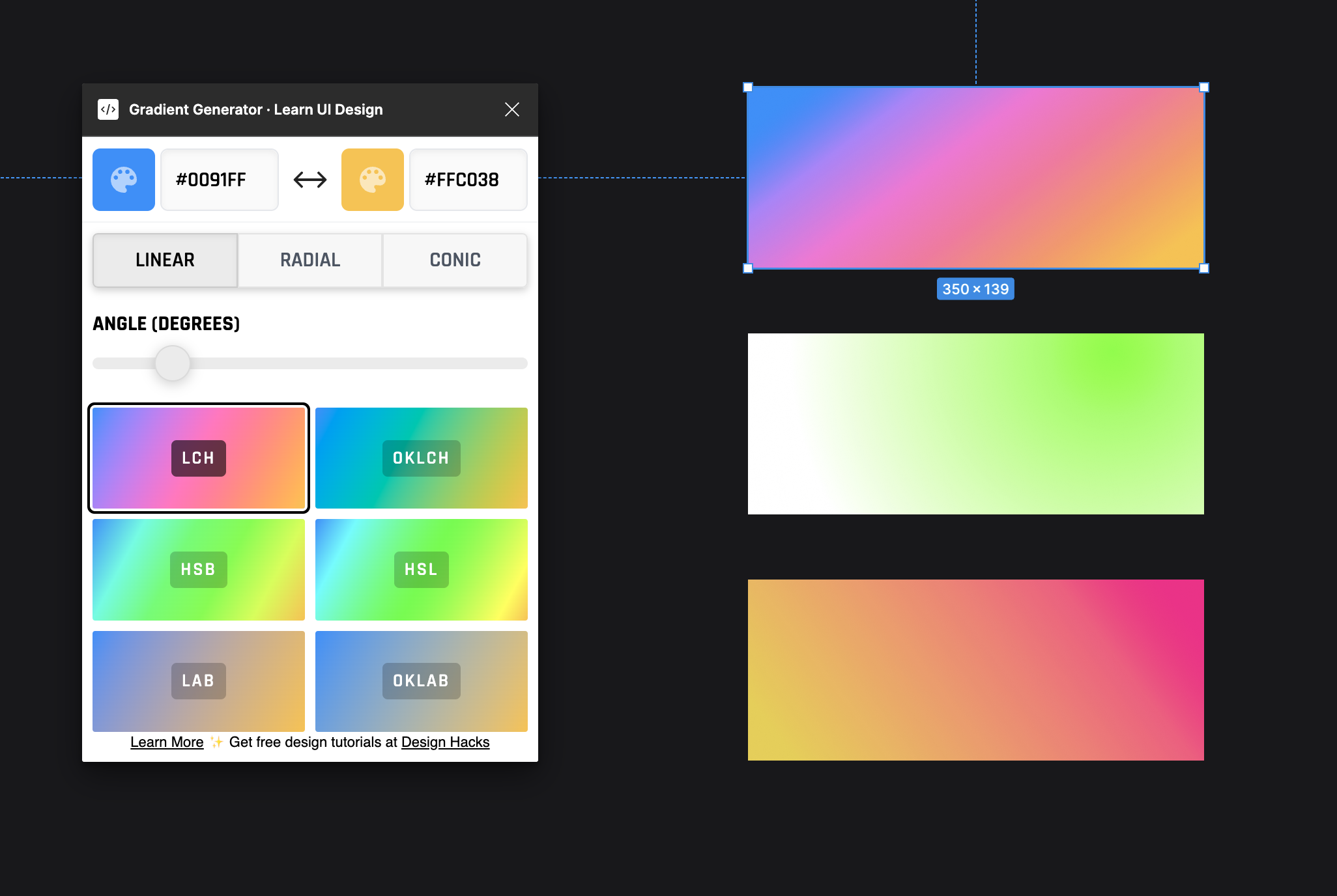
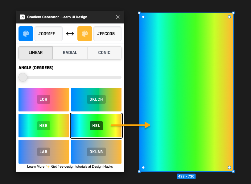
One of the topics he’s covered at length is what makes a background gradient visually appeasing and what makes them, well ,dull (links). A lot of it comes down to the way we interpolate between the two colour endpoints: that is, the path the gradient takes as it moves from colour 1 to colour 2 and passes through a series of intermediate stops. The “colour space” used to interpolate between the two colours will influence the nature of this path, and different colour spaces than the standard RGB can often yield much more interesting results. Using the standard RGB colour space can often result in the path crossing through a bit of a dull and grey area, which doesn’t look great. See below:

One reason for this is that we are simply interpolating between values for R, G and B. This isn’t taking into account the luminosity of the colours - basically how much light we perceive the colour to be emitting. So there’s no consistent change in luminosity and the midpoint feels ‘off’.
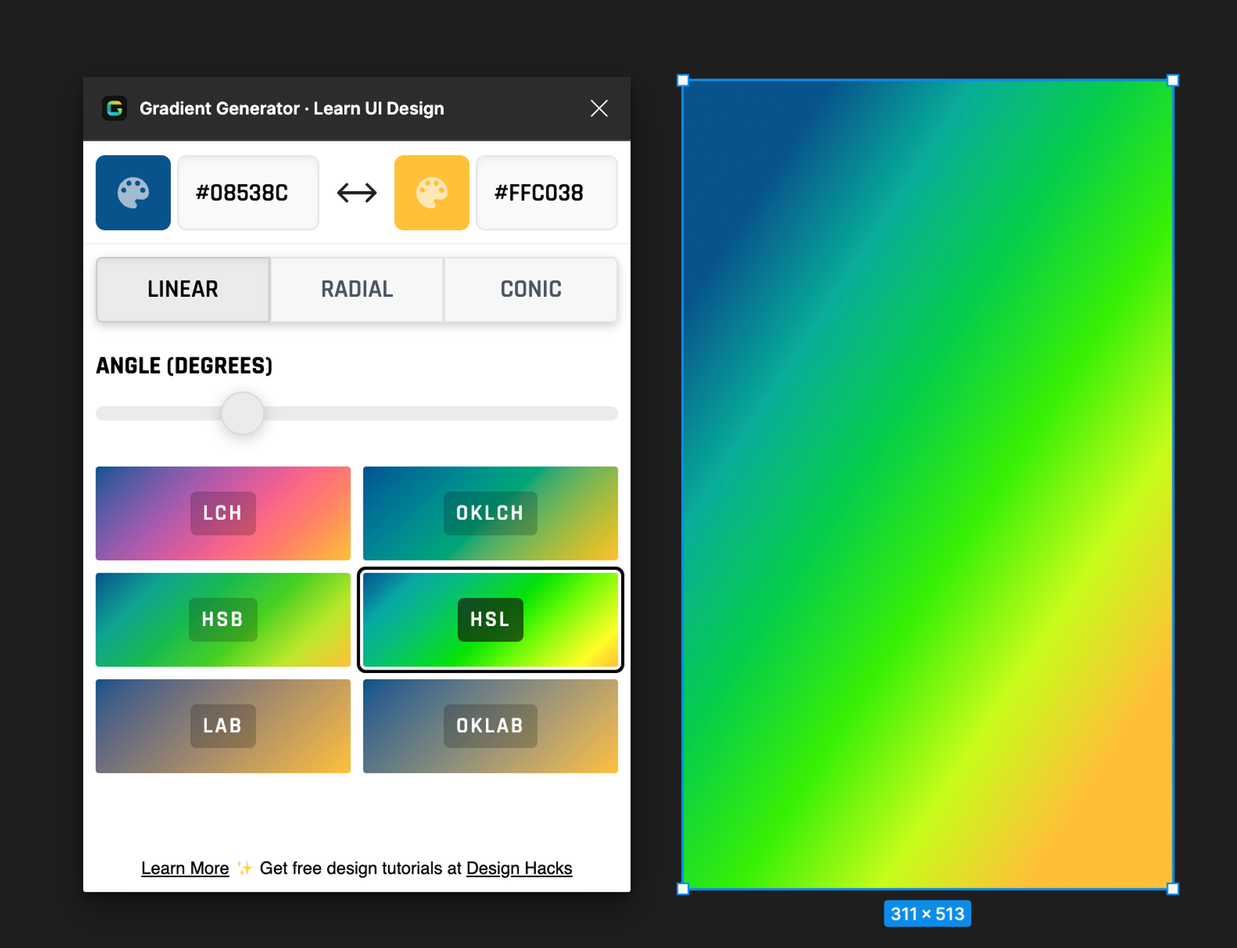
Let’s take a look at the result if we use a colour space based around luminosity, the interpolation should be much smoother in this regard:

This was using the LCH colour space instead of RGB and, as you can see, it’s quite different! Anyway, I won’t go into too much more detail on the theory behind all this as Erik has covered it at length in both his course and his online tool.
After generating some nice gradients with his online tool, I thought: “hey wouldn’t it be cool if we could do this directly in Figma, applying the gradients to my layers, seeing live changes as I tweak the gradient settings?!”.
So, I reached out to Erik with this offer and he said “sounds good, I'll whip up some designs for a plugin version”, and off we went.
Setting up the Figma Plugin Development Environment
From the start, I knew I wanted to use my “go to” stack for this project, React + Tailwind. The first step then was finding a decent starter template to kick things off, I settled on this one https://github.com/nirsky/figma-plugin-react-template/tree/main, which saved me from setting up webpack myself for a React project that runs as a Figma plugin. I then tweaked this slightly to get Tailwind going (can’t live without Tailwind!).
At this point, it’s worth discussing how Figma actually runs and manages plugins. The starting point is the manifest.json file, which provides the basic configuration, let’s take a look at a bare bones version:
{
  "name": "<YOUR PLUGIN NAME HERE>",
  "id": "<unique id when publishing>",
  "main": "dist/code.js",
  "ui": "dist/ui.html",
  "editorType": ["figma"],
  "documentAccess": "dynamic-page"
}
The main entry is the js file that will be used by Figma as the entry point to run the plugin. Here, it’s a webpack compiled version of a controller.ts file, which is separate from the React application code. This main file will have access to the global figma context, allowing it to perform actions within the actual figma canvas e.g. modifying layers.
The ui field is effectively expecting a html file for the plugin’s UI window. In this case, the webpack setup compiles my React app, bundles it and then injects it directly into <script> tags in a html file which is output to dist/ui.html.
So, I have a plugin directory with typescript files for interfacing directly with the Figma canvas (e.g. controller.ts), and another directory for a typical React application structure (index.html, index.tsx entry point and App.tsx for the root component etc).
Then with npm run dev , the plugin entry point (controller.ts) and the react app are both built and output into the files the manifest expects. I was then able to run the actual plugin within Figma by importing this manifest file:
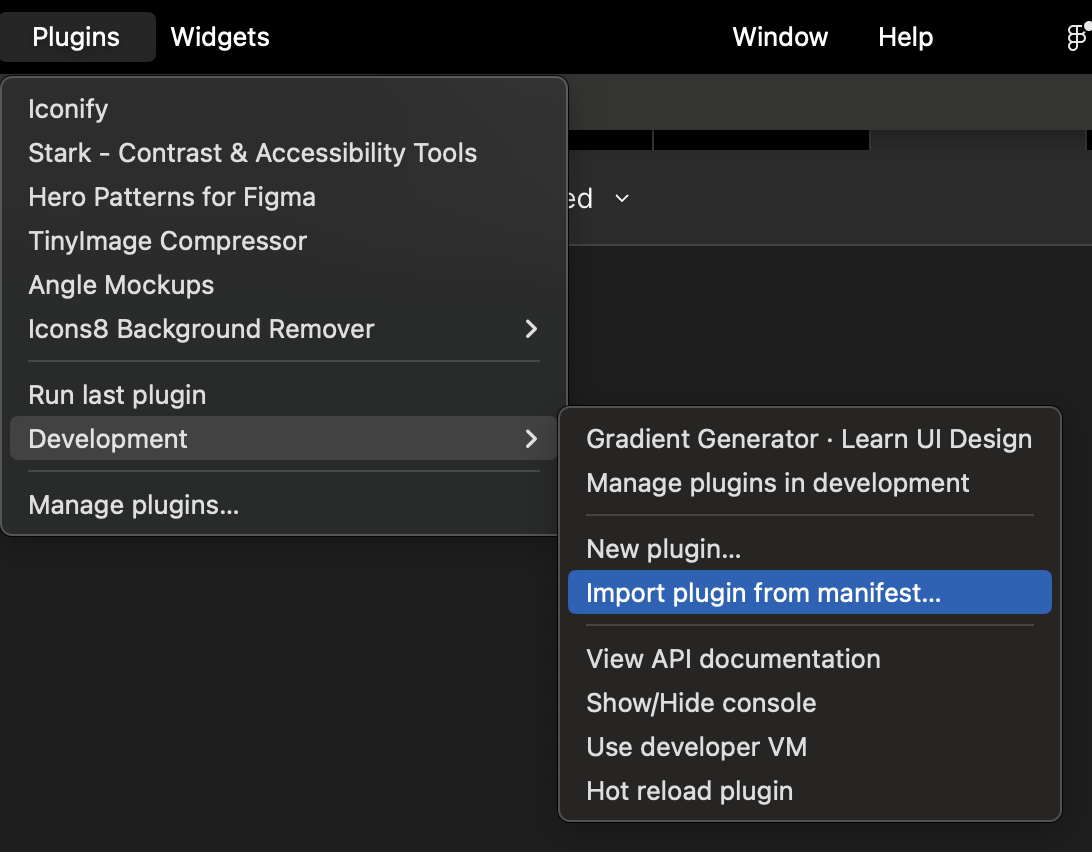
Ok cool, Figma then remembers this selection as a “development plugin”, and because npm run dev is set up to watch the files and recompile on changes, I can change code and see the changes in Figma without having to reimport the manifest etc 🙂
How the plugin window communicates with the Figma canvas
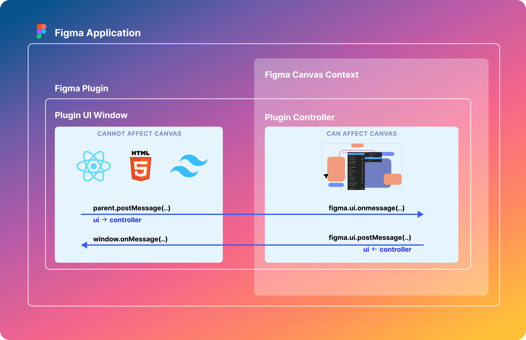
With Figma plugins, it’s useful to think in terms of two “contexts”: the main Figma application context (what we think of when think of “Figma” in general, which deals with everything in the canvas like layers and frames etc), and the specific context of a plugin’s UI window.
The plugin window’s context has no access to anything on the Figma canvas. However, the controller.ts file is run within the main Figma application context, hence why it can call methods directly on the figma global context. So for simplicity’s sake, let’s refer to them as the ‘plugin ui context’ and the ‘plugin controller context’.
As the plugin window cannot do anything useful on the canvas itself, it must ask the controller context “Hey, do you mind doing this in the canvas for me?”. This is done by posting messages on the plugin window’s parent (from within the react app) and then handling these in the plugin controller context using the figma.ui.onmessage method.
So, we have situation like the image below in order to handle communication:
Generating the gradients
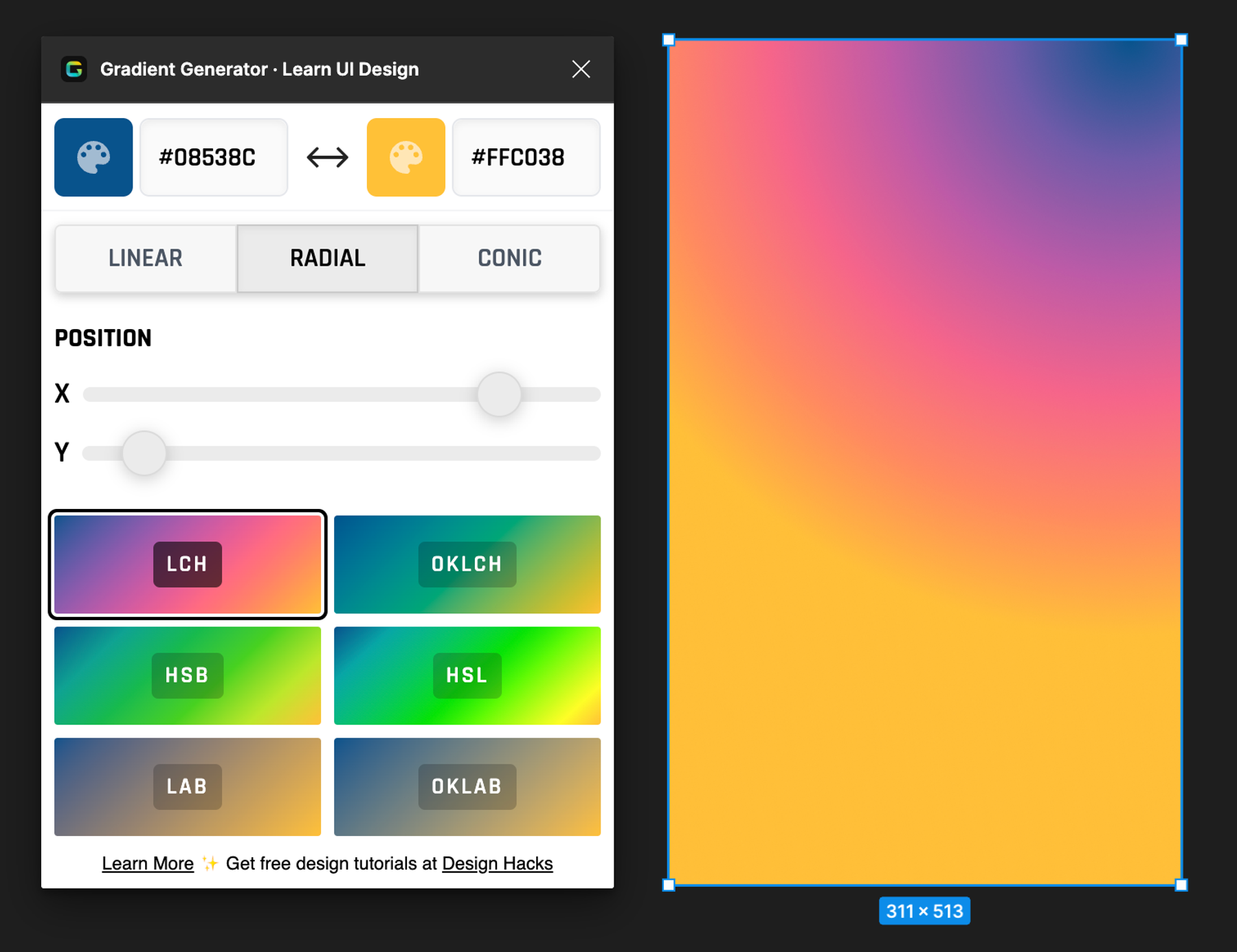
We decided to go with 6 colour spaces for gradient generation: LCH, OKLCH, HSB, HSL, LAB and OKLAB. You can read more about these spaces here.
After Erik came up with some designs, I fleshed out a basic UI for the plugin window, which included:
- two colour pickers for the endpoints of the gradient
- sliders for the gradient angle and position
- a toggle group for switching the gradient type (linear, radial, conic)
- a radio group with 6 options for choosing the colour space to interpolate with
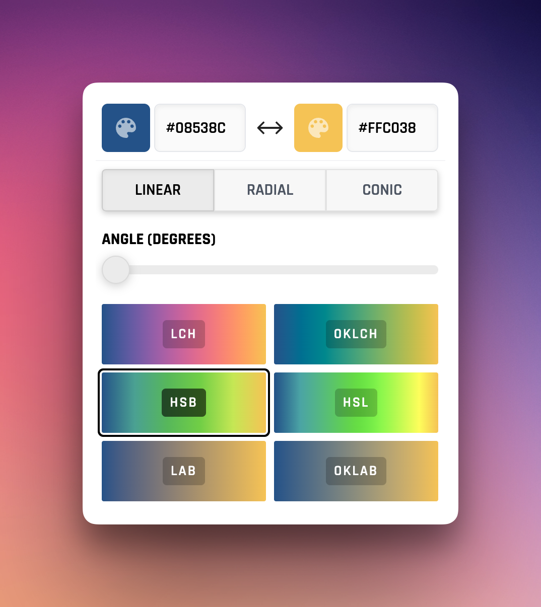
For the last 3 of these components, I started with some Radix primitives. (I’m loving Radix’s approach of providing unstyled component templates, with all the boilerplate functionality built in, so that I can just copy, paste, then modify as necessary to get the exact design I want. So much better than wrestling with opinionated component libraries!)
Since the plugin window is effectively running in Chrome, we could use the CSS colors level 4 interpolation to apply a background gradient to each of our colour space buttons, giving us a preview of how the gradients look expressed in the different colour spaces. For example, the background of the LCH radio option could be specified with:
const cssGradientLCH = useMemo(
  () =>
    `linear-gradient(in lch ${gradientAngle}deg, ${firstColor}, ${secondColor})`,
  [firstColor, secondColor, gradientAngle],
)
However, the Figma canvas does not have the concept of gradient interpolation in different colour spaces. Instead, it has a predefined standard for how different fills are applied to layers, namely using Paint objects. Specifically, GradientPaint lets you define different ‘color stops’ along the way to express a gradient, so if we supply a few intermediate colour stops of our generated gradient, we can replicate the visual of the css gradients in actual Figma layers.
I then needed to structure this colour data in a format that Figma could understand, including information on the colour stops and gradient type (linear, radial, angular) etc.
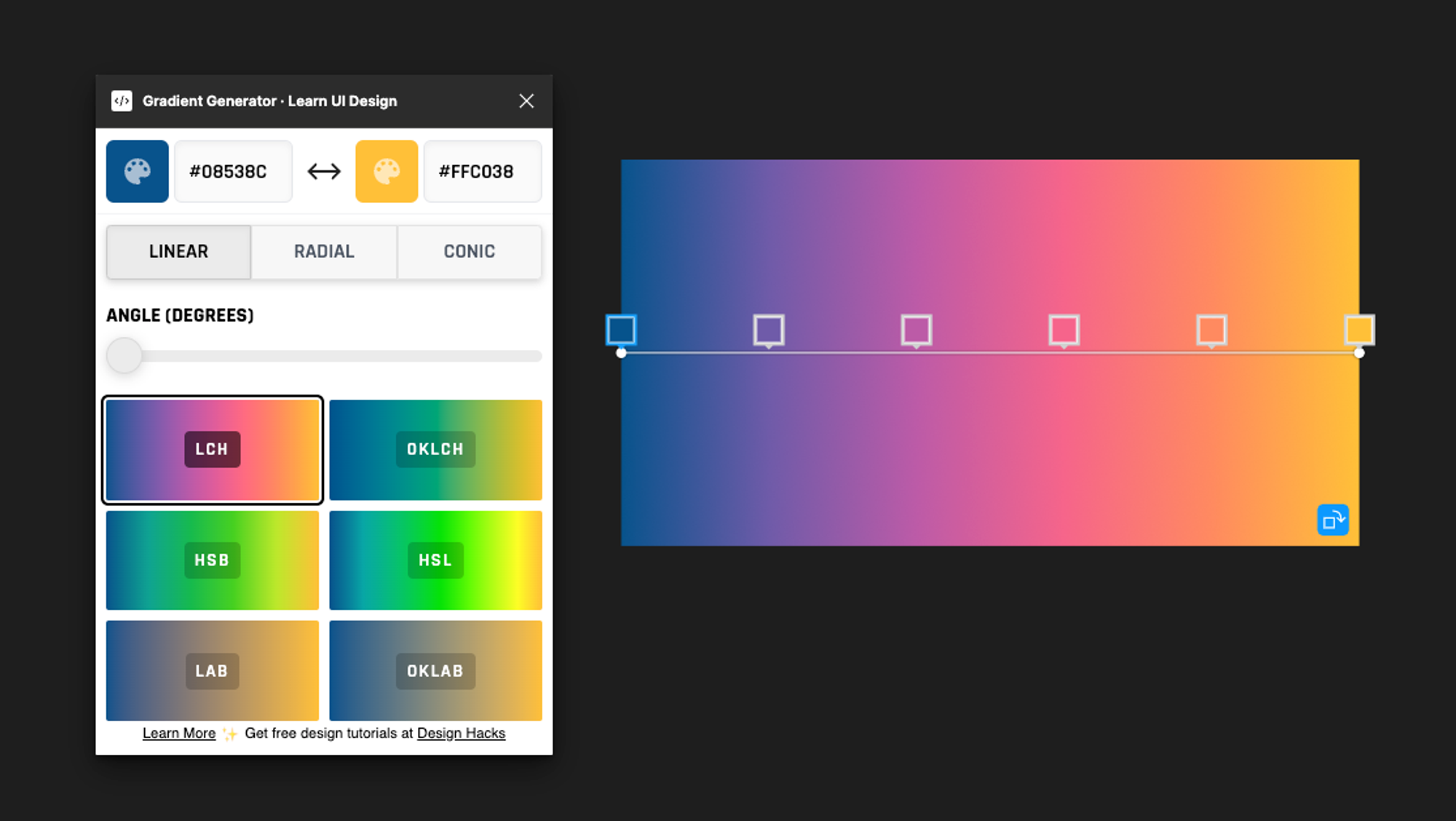
Let’s start with the simplest case, a linear gradient from left to right.
I used the culori npm library to take the two colour endpoints (as hex values) and interpolate between them based on the chosen colour space, generating intermediate colour values. We found that beyond 6 “stops” there wasn’t much more benefit. The following snippet shows how to build an array of intermediate colours on the chosen interpolation path.
// Inside a React component
import { samples, interpolate } from 'culori'

const colorStopObjects = useMemo(() => {
  const interpolatorFn = interpolate(
    [firstColor, secondColor],
    colorSpaceMethod,
  )

  const sampleStops = samples(NUMBER_OF_STEPS)

  const individualColorObjects = sampleStops.map(interpolatorFn)

  return individualColorObjects
}, [firstColor, secondColor, colorSpaceMethod])
The culori library helps to build an interpolator function based on the chosen method e.g LCH. The next step was to specify a set number of sample stops spread evenly between 0 and 1, so that the interpolator function could be called with how far along to interpolate between the two endpoints. For example, 0.25 would be a quarter of the way along the path. With these interpolated points, I just needed to format these in a way that Figma would understand when it came down to applying GradientPaint.
const figmaColorStops = useMemo(
  () =>
    colorStopObjects.map((color, index) => {
      const position = index / (NUMBER_OF_STEPS - 1)

      let converted = converter('rgb')(color)

      // Clamp in case the converted values fall outside the 0-1 range
      converted = clampRgb(converted)

      return {
        position,
        color: { r: converted.r, g: converted.g, b: converted.b, a: 1 },
      }
    }),
  [colorStopObjects],
)
Applying the gradients to layers
Figma will be expecting colours with r, g, b, a values ranging between 0 and 1 (not the usual 0-255 like css), as well as its defined position along the gradient line.
With this data ready, it was time to send it over to the plugin controller context, which could actually do the job of building the GradientPaints and applying them to selected layers.
const onApply = useCallback(() => {
  parent.postMessage(
    {
      pluginMessage: { type: MsgType.APPLY_GRADIENT, data: figmaGradientData },
    },
    '*',
  )
}, [figmaGradientData])
The message must specify that it is, indeed, a plugin message, as well as a type (any name will do here (I’ve just created my own MsgType enum for reusability) and a data arg containing all the info.
Meanwhile, back at the controller.ts ranch, a listener was set up for this exact message type:
figma.ui.onmessage = async (msg) => {
  if (msg.type === MsgType.APPLY_GRADIENT) {
    HandlerMap[msg.type](msg)
  }
  // ...
}
This HandlerMap is just a cleaner way of organising the various message handlers, one of which is of course for applying the gradients. It takes the data from the message and uses it to apply fills to layers.
function handleApplyGradient(msg) {
  const { data, liveUpdate = false } = msg;
  const { stops, gradientType } = data;

  // Get all the selected layers that support fills
  const fillableLayers = figma.currentPage?.selection.filter((layer) => 'fills' in layer);

  fillableLayers.forEach((selectedLayer) => {
    // if there are no fills, add the new fill
    const fills = selectedLayer.fills as Paint[];

    const newFill: Paint = {
      type: gradientType,
      gradientStops: stops.map((colorStop) => colorStop),
      gradientTransform,
    };

    if (fills?.length === 0) {
      selectedLayer.fills = [newFill];
    } else {
      const newFills = [...fills];
      newFills[newFills.length - 1] = newFill;
      selectedLayer.fills = newFills;
    }
  });

  figma.ui.postMessage({
    type: MsgType.APPLY_GRADIENT,
    message: `Applied gradient to selected layer.`,
  });
}
This snippet demonstrates using the figma global context to access the user’s current page, all of the selected layers and then filtering them down to those that support ‘fills’ (this is most of them to be fair). For each one of these layers, a Paint object which will correspond to a type (e.g. GRADIENT_LINEAR) along with the gradientStops, which are the colours in the r,g,b,a format converted earlier.
Boom! Now when clicking one one of the colour space options, it was visible as the fill of our selected layer!
That was the proof of concept working, it was then time to add some polish: supporting extra gradient types as well as the gradient angle and positioning.
That was the proof of concept working, it was then time to add some polish: supporting extra gradient types as well as the gradient angle and positioning. I thought it would be plain sailing from there on. I was wrong. Getting the angle of the gradient looking correct turned out to be a bit (a lot) trickier than expected, and so, I realised I had to brush the dust off some high school (and even a little college) level maths! I realise that this is probably overkill for those just wanting to get going with building a Figma plugin, so I put all the maths stuff in [Extra Reading](link to end) at the end.
So, for now let’s skip to the part where I’d figured out 2d transforms in Figma and the angle slider worked as expected.
After this, I was able to hook up the toggle group component to change the gradient type to GRADIENT_RADIAL or GRADIENT_ANGULAR , adding in sliders to modify the position of the gradient too:
Nice, this covered off the functionality of actually applying the gradients we wanted to the layers 🙂 The next step was to ensure smooth live updating in the Figma canvas.
Live Updates in the Canvas
We wanted an experience where changes in the plugin window controls were reflected instantly in the canvas, so the user could tweak the colours, angle and positioning to get their gradient just right, without any waiting around.
This was pretty straightforward with React, I basically just:
- set up a
useMemowhich returns a structure with all the required info about the gradient - Set up a useEffect which just puts this info on a ref
- Set up a memoised debounced function that sends the data on this ref to the plugin controller context to actually apply to layers (I used the
refas the actual gradient data would trigger a dependency change inuseMemowhich would rebuild the debounced function). - Set up a useEffect to call this debounced function every time the gradient data changes.
This way we could play around with the debounced delay until we got a smooth updating effect without overloading the plugin controller context with update calls as the controls are rapidly changed (think dragging the slider left and right quickly). Here’s a snippet of this:
const figmaGradientData = useMemo(
  () => ({
    stops: figmaColorStops,
    gradientType,
    positionX,
    positionY,
    angleDegrees: gradientAngle,
    colorSpaceMethod,
    firstColor,
    secondColor,
  }),
  [
    colorSpaceMethod,
    figmaColorStops,
    firstColor,
    gradientAngle,
    gradientType,
    positionX,
    positionY,
    secondColor,
  ],
)

const debouncedApplyGradient = useMemo(
  () =>
    debounce(
      () => {
        parent.postMessage(
          {
            pluginMessage: {
              type: MsgType.APPLY_GRADIENT,
              data: gradientDataRef.current,
              liveUpdate: !initialLoad,
            },
          },
          '*',
        )
      },
      25,
      { leading: true, trailing: false, maxWait: 50 },
    ),
  [initialLoad],
)

useEffect(() => {
  gradientDataRef.current = figmaGradientData

  if (initialising) {
    return
  }
  debouncedApplyGradient()
}, [debouncedApplyGradient, figmaGradientData, initialising])
And so, settling on a 25ms debounce delay with a max wait of 50ms, we got the smooth effect we were looking for:
Nice, almost there! Just one more key bit of functionality we wanted…
Saving Data to Figma Layers (+Rehydrating)
The final thing was the ability to actually repopulate the plugin UI with the gradient data we already saved on a layer earlier. Why is this needed? Well, let’s say the user applied Gradient A to layer 1, then a completely different Gradient B to layer 2. If they thought “hey I want to tweak that Gradient A slightly”, it would be pretty annoying if they’d lost those exact settings and the UI only remembered the more recent Gradient B data. They’d have to basically start again!
Luckily, Figma has a pretty useful way of saving any kind data within a layer - the setPluginData method on a layer. This expects a key and a value as args and is saved on that layer in a way that only the calling plugin can access again later (no other plugins can read this specific data). The value must be a string so JSON.stringify was used here.
As expected, there’s also getPluginData to be called with a key. So, every time we applied a gradient to a layer, we also stringified and saved all the associated settings to it. Then later, through the use of figma.on('selectionchange', ...) , we could basically say:
“Hey, a new layer has been selected, let’s call getPluginData and see if we’ve ever saved any gradient data to this layer. Oh, we have? Cool, let’s parse this and update the plugin UI with these same settings!”
And we’re there!
Wrapping Up + Publishing
At the end, there were just a couple of smaller details to finesse at the end, mainly around “initialisation logic”; basically the behaviour when the plugin start up - checking for selected layers, hydrating the gradient data if there is any or applying a default gradient right away.
Once this was all tidied up, Erik and I ran though it a good few times, ironed out the usual little bugs here and there, and then were ready to hit Publish!
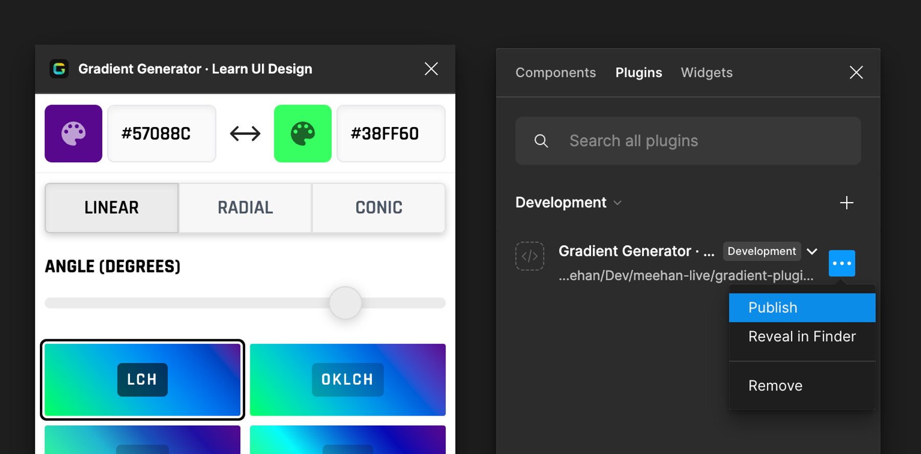
This is typically done from the actual Figma desktop app rather than on their website. Assuming you’re logged in on the desktop app, you can go to
Plugins -> Development -> Manage Plugins in Development to bring up a screen like below, where you can find the “Publish” option inside the ellipsis menu.
This takes you down a path where you can put in any collaborators, as well as resolve any issues with your manifest file. We found here that you need add a networkAccess field and populate with any and all domains that your plugin will access at all, that meant google fonts domains for us so we could actually load a different font, as well as Erik’s domain so we could link to it in the plugin.
Erik whipped up a plugin featured image, along with an icon and we were good to go! The approval process said it could take anywhere from 2-5 days but the next day we found out it had been approved and was live in the Figma community 🎉!
And that’s a wrap, this was how we went from conception to a published plugin. I hope someone out there find this useful, and feel free to get in touch with any further questions!
Again, you can find the published plugin live here
Thanks for reading! And if anyone is interested, there’s a little extra below about some of the unforeseen maths I had to wrestle with...
Supplementary Material
The Maths Heavy Part - 2D Transforms in Figma
When playing with gradients directly in the Figma canvas, we can simply click and drag the endpoints of the gradient, stretching it and rotating it as we desire. However, when doing this via the plugin api, it's not as simple as just saying "hey turn it 30 degrees pls".
The gradientTransform property is a Figma Transform type, a 2D matrix, used to specify how the gradient is transformed in two dimensional space. This data structure represents translation, scale, shear and rotation. In the realm of 2D graphics, these are 3x3 matrices, but Figma only requires a 2x3 matrix, known as an “affine transform”, where the bottom row is assumed to be [0, 0, 1]. You can read about Figma’s implementation of this in their API docs.
Without getting too much into the weeds of 2D graphics, the values in this matrix affect how each coordinate on a shape is transformed from its starting to final position. Let’s look at the case where we want no transformation at all, the “identity matrix”:
[[1, 0, 0],
 [0, 1, 0]]
Here, the two values of 1 at positions 0,0 and 1,1 are saying scale this by a factor of 1 in the x direction and y direction respectively (effectively no scaling).
If we want to apply nothing but a translation (shifting in the x and y direction), we would have a matrix like so:
[[1, 0, tx],
 [0, 1, ty]]
Here, tx and ty represent how much we shift in the x and y direction.
Now, a rotation matrix, doing nothing but rotating the body about the origin (that is 0,0 and this is really important), looks like this:
[[cos(θ), -sin(θ), 0],
 [sin(θ), cos(θ), 0]]
You can see that this already looks a little complicated, just rotating it by an angle means we still need to modify values affecting the scale and shear. Feel free to dig into the details of affine transforms and why this is the case here.
Ok, so using these as guidelines, I implemented the slider to correspond to a rotation angle (in degrees) and tried to apply this transformation to the gradient. After converting the angle to radians (the Transform property expects this), then building the affine transform just for a rotation, it would look like this with zero rotation:
And then, once there was some angle applied:
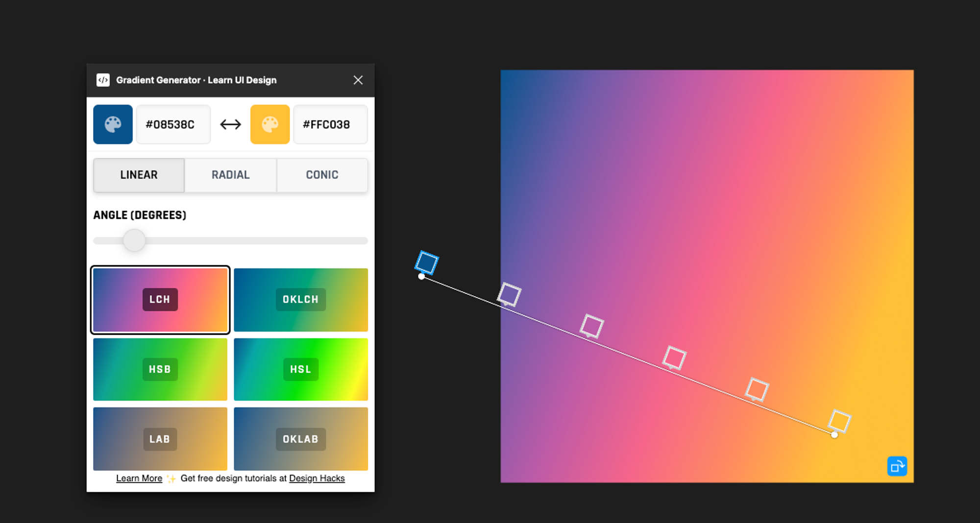
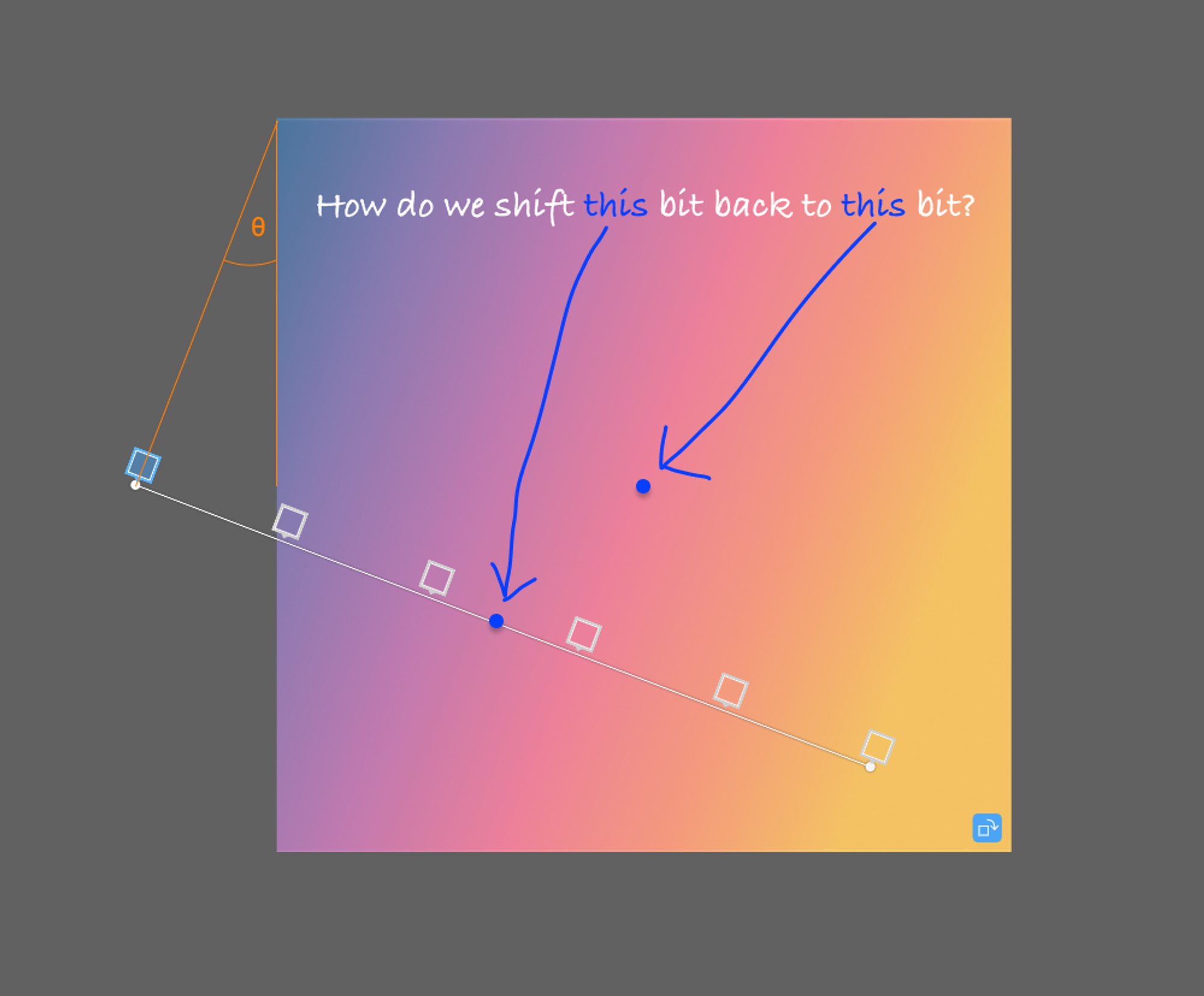
Ok something happened, but right away it’s obvious it’s not what we wanted. This is because the origin of rotation is taken at 0,0 - the top left of the shape itself. So the “line” of the gradient which goes about the horizontal midpoint is swung out of position.
After little bit of struggle, it seemed that the solution was just “hey, why don’t we just use the translation properties of the matrix to shift it back into place after rotating it?”. So that’s what I did.
Now, a super important point here is that no matter the shape of the rectangle layer, when dealing with transformation matrices, Figma will pre-scale both the x and y coordinates so that no matter what, the size of the shape goes from 0 to 1 in the x direction and 0 to 1 in the y direction. Hence 0.5, 0.5 will always be the midpoint of the shape. This means that regardless of the aspect ratio of the shape, we know it will be treated as a 1 by 1 square for transformations, then scaled back out after. This actually simplifies things a lot. Thinking of it as a square, we can use trigonometry to determine how much to shift it back.
This is where some trigonometry comes in. We can break this down in terms of the angle of rotation θ and use it to deduce how far the centre of the line will have shifted after the rotation.
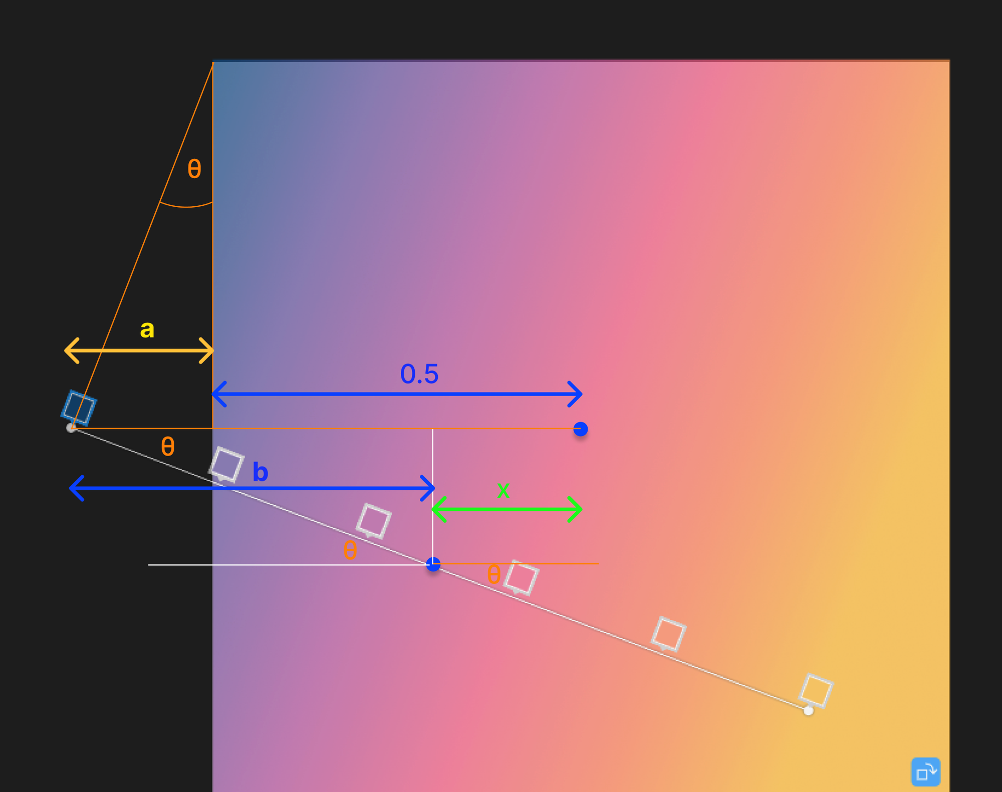
From this image, we effectively need the value for x to work out how much it has shifted horizontally. We can see clearly here that
x = 0.5 + a - b
So that just leaves us with working out a and b. Well, with some trig here, we know that the hypotenuse is 0.5 in length (it’s half the length of one of the square’s edges which is normalised to 1). So a must be 0.5sin(θ) and b must be 0.5cos(θ).
We can repeat this logic for how much the centre must have shifted vertically, and then we know what we need to use as the translation values of the affine matrix to put it back in position.
const tx = 0.5 - 0.5 * cosAngle + 0.5 * scaledSin
const ty = 0.5 - 0.5 * sinAngle - 0.5 * scaledCos
Nice, this worked and then when we rotated the gradient with these values in the affine transform, it would appear as if it was rotated about the centre of the shape rather than 0,0.
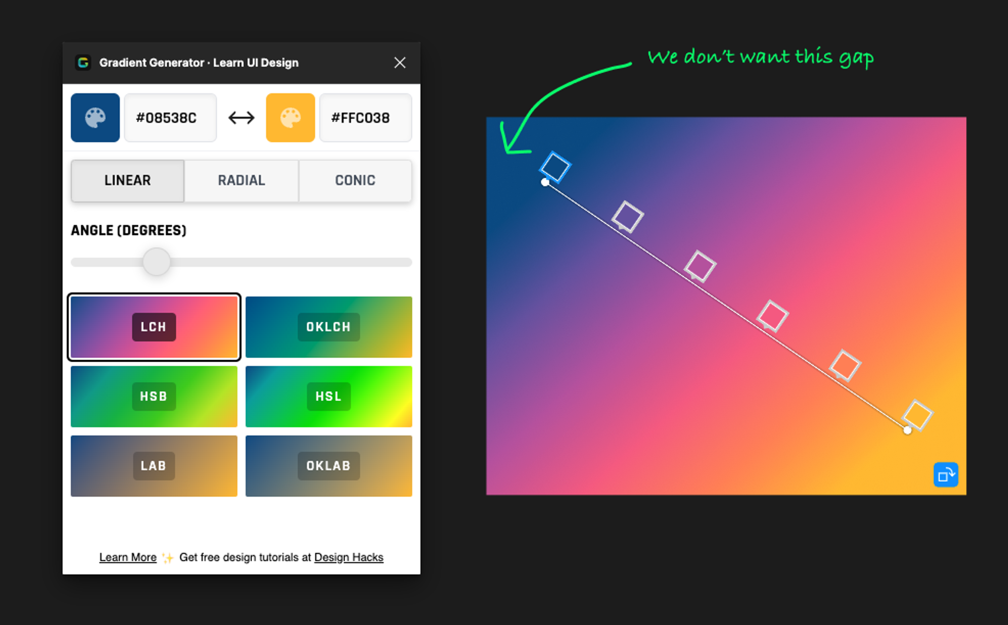
With this issue sorted, one thing that didn’t feel quite right was the fact that when the gradient line was rotated, it would not extend to fit flush with the edges of the shape. This is because the line simply went through a rotation transformation without any scaling, therefore it remained at a length of 1. This is fine when the angle is 0 or 180 degrees, but for anything else there will be a gap at the edges, leading to portions of the shape being completely the endpoint colours.
To solve this, it was best to first think about the extreme case, when there was a 45 degree rotation. This would lead to the biggest gap (remember, Figma internally scales the x and y coordinates to be 0 → 1 so it’s effectively a square). In this situation, we know that the length of the line is 1, but the length of the full diagonal is √2 based on Pythagoras: so for the line to stretch corner to corner here it must be scaled by √2 / 1, so just a factor of √2 . By this logic, even if the rotation is slight, we should be able to work out the length it should be based on trigonometry, then simply apply a scaling factor to the line.
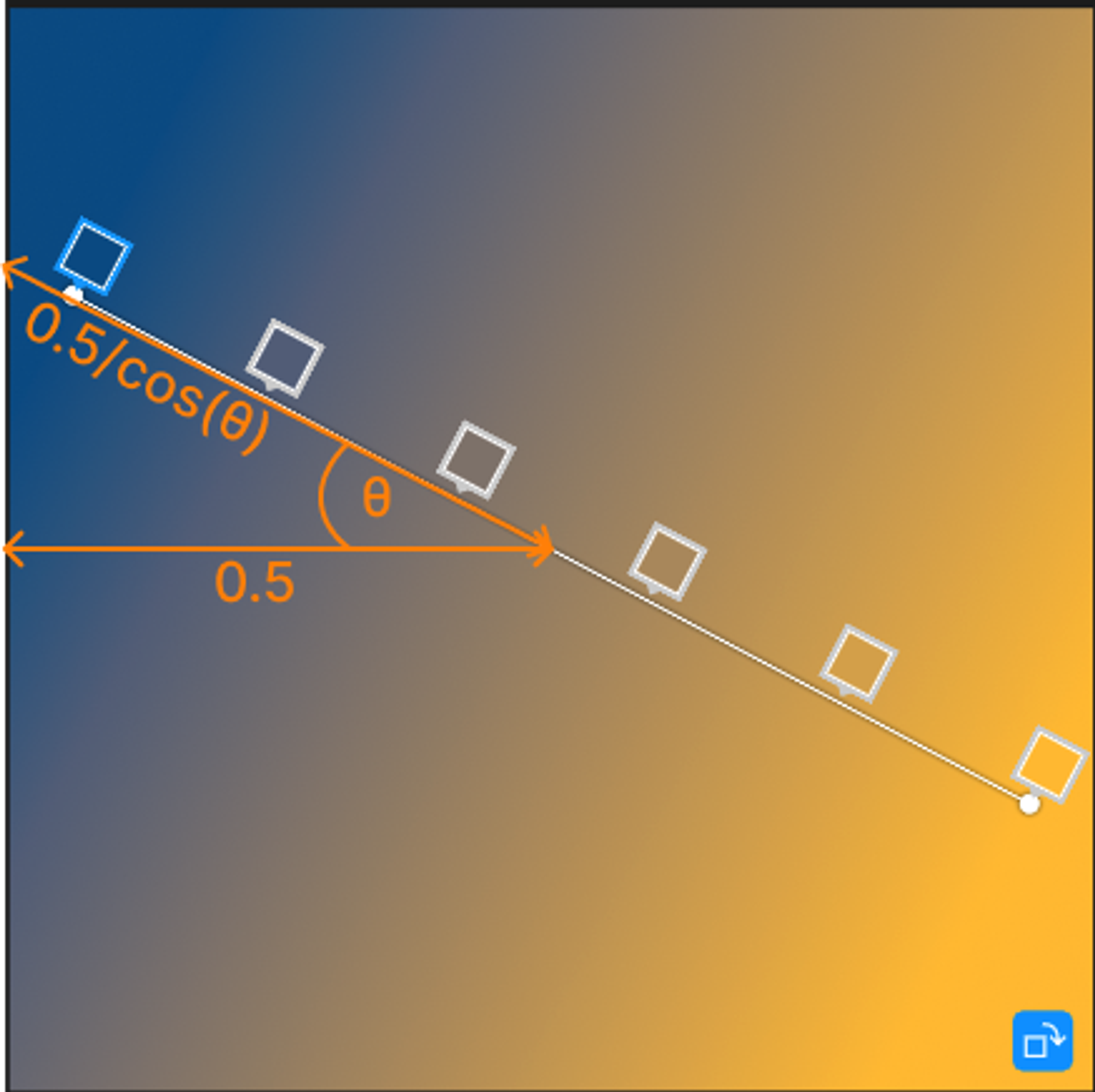
From this diagram, we can see that if we isolate half of the line, it’s 0.5/cos(θ) / 0.5 to get the scaling factor, which is the same as 1/cos(θ). So this scale applied to the full line would result in it fitting flush to the edges. Now, the actual scaling factor in the Figma affine transform is inverted, so 0.1 would make it 10x bigger, this means we need to invert the scaling factor we calculated earlier, which just gives a simple cos(theta). Of course, once the angle exceeds 45deg, it would be the sin rather than cos, so to alleviate this, I just normalised the angle so that I could always use cos 🙂. Here’s my function for calculating the required scale.
function calculateRotationVars(angleDegrees: number, nodeType: string) {
  let angleRadians = (angleDegrees * Math.PI) / 180;

  // Swap the direction of rotation from CSS angle into proper transformation angle
  // (counter clockwise should be positive, in CSS it's the opposite)
  angleRadians *= -1;

  let normalizedAngleRadians = Math.abs(angleRadians) % (Math.PI / 2);
  if (normalizedAngleRadians > Math.PI / 4) {
    // Adjust angle after 45 degrees to scale down correctly towards 90 degrees
    normalizedAngleRadians = Math.PI / 2 - normalizedAngleRadians;
  }

  const sin = Math.sin(angleRadians);
  const cos = Math.cos(angleRadians);

  let scale = 1;

  if (['RECTANGLE', 'FRAME'].includes(nodeType)) {
    const normalisedCos = Math.cos(normalizedAngleRadians);
    scale = normalisedCos;
  }

  return { sin, cos, scale, angleRadians };
}
Perfect, the only thing to account for now is the fact that because we’re also scaling the line to make it bigger as it rotates, this will affect our earlier logic to shift the centre of the line back to the centre of the shape. This is not too bad, it just means we also need to scale the sin(theta) and cos(theta) from our earlier equation. So bringing it all together, here’s the function for actually calculating the affine transform required so that the line would effectively:
-
rotate about its centre and
-
stretch to always fit flush with the edges of the surrounding rectangle
function generateGradientTransformForRotation(opts: GradientTransformOpts): Transform {
const { angleDegrees, node } = opts;

const { type: nodeType } = node;

const { sin, cos, scale } = calculateRotationVars(angleDegrees, nodeType);

const scaledCos = cos * scale;
const scaledSin = sin * scale;

// Compute the translation to keep the gradient centered after scaling
const tx = 0.5 - 0.5 * scaledCos + 0.5 * scaledSin;
const ty = 0.5 - 0.5 * scaledSin - 0.5 * scaledCos;

return [
  [scaledCos, -scaledSin, tx],
  [scaledSin, scaledCos, ty],
];
}
I hope this makes sense!
Later down the line there was also some tweaking the affine matrices to ensure the radial gradient was always circular, as well as multiplying two affine matrices together for the conic gradient to get the desired effects of both. Even for the “supplementary material” I’m sure this is a bit too much detail so if anyone is interested in that stuff, don’t hesitate to ask!
Peace ✌🏽